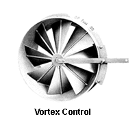
Vortex Inlet Damper


Design 3 - Vortex Control Rotation Changing Insructions

  1. Lay Vortex Damper on work surface with blades in the closed position, and with air leaving side up.
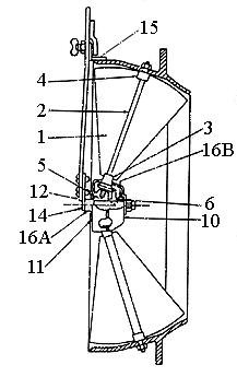
  2. Remove nut from center hub assembly.
  3. Remove Gear Cover Back (item 10) and Drive Gear (item 6).
  4. Remove Operating Lever (item 12) from current holes in the Lever Bracket (item 14) and re-bolt onto other two holes in Lever Bracket (item 14).
  5. Rotate Blades (item 1) so they overlap in the opposite direction.
  6. Replace Drive Gear (item 6), Gear Cover Back (item 10) and nut.
  7. Several attempts may be necessary to get all blades (item 1) lined up and the Operating Lever (item 12) in the correct position to operate totally open and closed. It may be necessary to bend the blades slightly to get a complete seal with one another.

ROTATION

Fan Wheels

  • Rotation is determined looking from the back side (or motor side)

Vortex Dampers

  • Rotation is determined looking through the Vortex Inlet Damper

CCW (Counter Clockwise) Vortex Dampers

  • Looking through the Vortex Inlet Damper, the fan wheel should be rotating CCW, the Operating Lever will move CW to close the Damper, and CCW to open the damper.

CW (Clockwise) Vortex Dampers

  • Looking through the Vortex Inlet Damper, the fan wheel should be rotating CW, the Operating Lever will move CCW to close the damper, and CW to open the damper.

NOTES:

  • CW Fan Wheels will have CCW Vortex Inlet Dampers.
  • CCW Fan Wheels will have CW Vortex Inlet Dampers.


Go Back to
DF Fan Home Page
DF Fan Services, Inc.
495 Wegner Drive
West Chicago, IL 60185
Phone: (800) 876-1495
FAX: (630) 876-1497
e-mail: dffan@dffan.com

Get A Quote
Get more Information